Introduction
BIOMECHANICS is defined as the application of mechanical forces to the living organisms and the integration of forces and the body or system which includes forces that arise from within and outside the body (Tabers Encyclopedia Medical Dictionary).
Simply, it is application of mechanics (motion of bodies) to biologic systems.
Stress Analysis
Theoretical : Experimental
Mathematical Analysis : Strain Gauge
Finite Element Analysis : Holography Photoelasticity
The Finite Element Method (FEM) is a computerized numerical iteration technique used to determine the stress and displacements through a predetermined model.
The Finite Element Method is a numerical analysis technique used by engineers, scientists, and mathematicians to obtain solutions to the differential equations that describe, or approximately describe a wide variety of physical (and non-physical) problems. Physical problems range in diversity from solid, fluid and soil mechanics, to electromagnetism or dynamics. Hence FEA is being considered a part of the design process spanning across industries or domains, be it automotive, aerospace, medical, civil, and electrical etc.
The method was introduced in late sixties in the aerospace industry and was applied in dentistry in the early seventies.
With age, human teeth are weakened by caries, abrasion, malocclusion and fracture. Cavity preparation procedures and other treatments, due to reduction of tooth structure and loss of nutrients from dental pulp, exaggerate the fracture potential of the remaining tooth structure. Inappropriate treatments, such as unnecessarily wide cavity preparation increase the potential of further trauma and possible fracture of remaining tooth structures. Fracture potential may be directly related to the stresses exerted upon the tooth during masticatory function. An understanding of this relationship between the stresses in a tooth and its fracture potential should assist clinicians in eliminating or reducing the factors contributing to tooth fracture, thus maintaining the remaining tooth structure without fracture.[1] In an attempt to better understand the stresses in the tooth, a variety of methods have been used to predict tissue response to load.[2] These include theoretical mathematical techniques[3], photoelastic systems[4] and laser holographic interferometry[5]. However, these techniques have the disadvantage of only examining surface stress, whilst having the added problem of usually being supported by poor validation systems as judged by the current standards.[6] The finite element method can be applicable to the problem of the stress strain levels induced in internal structures. This method also has the potential for equivalent mathematical modeling of a real object of complicated shape and different materials.
FEM - Concept
Stress-Strain Relations (Hooke’s Law): A specimen of a specific diameter is subjected to a tensile or pulling force. The stress is calculated as force per unit area. The change in the gauge length is measured and the strain is evaluated as change in length per unit length. Stress and strain are linearly related up to the proportional limit. Hooke’s Law states that the stress is proportional to strain. The constant of proportionality is called the Young’s modulus or modulus of elasticity. The diameter of the specimen reduces as the specimen is pulled. The ratio of lateral strain to the axial strain is called the Poisson’s ratio.[7]
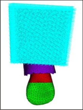
Finite analysis solves a complex problem by redefining it as the summation of the solution by a series of interrelated simpler problems. FE stress analysis technique models actual continuous structure with discrete element mathematical representation. This approach transforms the problem into one of matrix algebra which may be solved with the aid of digital computer. To create the model of tooth CT scan of the sections is combined to create a tree dimensional model. Figure 1 Is the ct scan image of central incisor. The first step is to subdivide (i.e. discretize) the complex geometry into a suitable set of smaller "elements" of "finite" dimensions when combined from the "mesh" model of the investigated structures. Each element can adapt a specific geometric shape (i.e. triangle, square, tetrahedron etc) with a specific internal strain function. Figure 2 and 3 is the Mesh model of the investigating structures.
Using these functions and the actual geometry of the element, the equilibrium equations between the external forces acting on the element and the displacements occurring on its nodes can be determined.
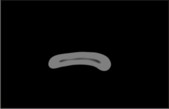 | Figure 1 A Ct Scan Image Of Maxillary Central Incisor
 |
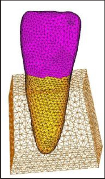 | Figure 2 Finite Element Model Of Maxillary Central Incisor With Supporting Structures
|
 | Figure 3 Fem Model Of Tooth With The Post And Core Assembly
|
Information required for the software used in the computer is as follows.
1) Coordinates the nodal points.
2) Number of nodes for each element.
3) Young's modulus and Poisson’s ratio of the material modeled by different elements.
4) The initial and boundary conditions.
5) External forces applied on the structure.
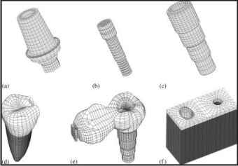
The boundary condition of these models is defined so that all the movements at the base of the model are restrained. This manner of restraining prevents the model from any rigid body motion while the load is acting.[8]
Figure 4 boundary conditions are applied
 | Figure 4 3d Model Of Maxillary Central Incisor With Post And Core Assembly And Applied Boundary Conditions.
|
It Includes:
Discretization of given problem
Developing element properties
Imposition of boundary conditions
Solution of assembled equation
Post processing of the results.
Mathematically:
F = Kx
Where,
F --- Force
K -------- Proportional constant
X -------- Distance of stretching
FEA is needed to:
1. Reduce the amount of prototype testing.
2. Computer simulation allows multiple “what if” scenarios to be tested quickly and effectively.
3. Simulate design that is not suitable for prototype testing (e.g. surgical implants as an artificial knee).
4. Cost saving
5. Time saving reduce time to market.
6. Creates more reliable, better quality designs.
Dental Applications
1) Finite element analysis has been applied to the description of form changes in biological structures (morphometrics), particularly in the area of growth and development.
2) Finite element analysis as well as other related morphometric techniques such as the macro-element and the boundary integral equation method (BIE) is useful for the assessment of complex shape changes.
3) The knowledge of physiological values of alveolar stresses is important for the understanding of stress related bone remodeling and also provides a guideline reference for the design of dental implants. Figure 5 3D FE model of a tooth/implant-supported system constructed for analysis.
 | Figure 5a 3d Fe Model Of A Tooth/Implant-supported System Constructed For Analysis
|
4) Finite element method is also useful for structures with inherent material homogeneity and potentially complicated shapes such as dental implants, restorative pins, post and core.
5) Analysis of stresses produced in the periodontal ligament when subjected to orthodontic forces.
6) To study stress distribution in tooth in relation to different designs.
7) To optimize the design of dental restorations.
8) To investigate stress distribution in tooth with cavity preparation.
9) The type of predictive computer model described may be used to study the biomechanics of tooth movement, whilst accurately assessing the effect of new appliance systems and materials without the need to go to animal or other less representative models.
10) To find out stresses induced with in the tooth, periodontal ligament and alveolar bone due to normal occlusal forces which may be a cause for non carious cervical lesion i.e. Abfraction. Figure 6 finite element model showing constraints and applied load [9].
 | Figure 6 Finite Element Model Showing The Constraints And The Applied Load
|
11) To study effect of adhesive layer properties on stress distribution in composite restorations and stresses induced by different techniques used for restoration.
12) To investigate the effect of thermal and mechanical loading on the resorted teeth.
Advantages Of Fem:
1. It is a non destructive method which employs simulation of conditions with greater accuracy.
2. The actual physical properties of the materials involved can be simulated. Thus this method is nearest one that could possibly get to simulate the oral environment in-vitro.
3. Can be applied to bodies composed of several materials.
4. The actual stress experienced at any given point can be measured.
5. Reproducibility does not affect the physical properties of the involved material and the study can be repeated as many times, as the operator wants.
6. Irregularly shaped boundaries can be approximated.
7. Mixed boundary conditions can be easily handled.
8. Analyzes complex geometry and it can determine stresses and strain through out a 3 dimensional component.
9. The ability to obtain accurately the stresses through out the structure under consideration.
10. Inclusion of any type of anisotropy (directional characteristics) and inhomogeneity is conceptually possible by inserting the appropriate distribution of material properties at the nodes of the elements.
11. FEM an engineering method of calculating stresses and strain in all materials including living tissue has made it possible to adequately model the tooth and periodontal structures for scientific checking and validating the clinical assumptions.
12. The finite element method offers an ideal method for accurate modeling of the tooth – periodontium system with its complicated three dimensional geometry. Abnormal stress levels may allow the clinician to estimate the tissue damage and implement therapeutic modalities sooner.[10]
13. The type of predictive computer model described may be used to study the biomechanics of tooth movement, whilst accurately assessing the effect of new appliance systems and materials without the need to go to animal or other less representative models.[11]
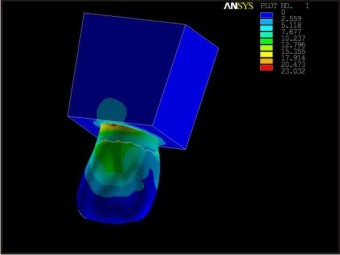
Using the finite element program ANSYS a study was conducted in the Department of conservative dentistry and endodontics, Bangalore, using a three dimensional finite element model of maxillary central incisor treated with root canal and post core to find out the difference in the stresses induced within the tooth,periodontal ligament and alveolar bone due to normal occlusal force directed in a palato-labial direction with cast post and core and with light transmitting post.The results of the study concluded that Stress transfer was more with in the post and core unit for the Custom cast post compared to the Light transmitting post, which had low stresses distribution with in post and core unit.Also the transfer of stresses to the tooth and supporting structure was more for the Custom cast post when compared to the Light transmitting post.
Maximum stresses were observed in the cervical region for both the posts systems, but at different locations. Finite Element Analysis for the Light transmitting post showed that the maximum stress concentration was at the post-core junction and all the fractures were at core level in Fracture Strength Test indicating a definite correlation between the level of maximum stress and mode of failure.[12]
Figure 7 Stresses in the tooth and supporting structures in 3D model of Custom cast post Figure 8 Stresses in the tooth and supporting structures in 3D model of Light transmitting post
 | Figure 7 Stresses In The Tooth And Supporting Structures In 3d Model Of Custom Cast Post
|
 | Figure 8 Stresses In The Tooth And Supporting Structures In 3d Model Of Light Transmitting Post
|
Disadvantages Of FEM:
Finite Element Analysis is an approximation method to represent both the deformation and the 3D-stress distribution in bodies that are exposed to stress. In addition to the FEM advantages, it has some disadvantages. For example, the mechanical properties of the materials are complicated, and it might not be possible to include the ideal properties into the model. For this reason some assumptions are accepted, and the FEM is based on them to simplify the real situation. Some errors are added to the solution of the problem due to assumptions. But the error percentage in the solution can be omitted. The first idealization is about material, and the materials are assumed to be linearly elastic, homogeneous, and isotropic. However, the material is not really linearly elastic, and the material properties and the geometry of the model change from one person to another. This makes the problem even more complex. On the other hand, forces or stresses that can cause plastic deformations in bone or teeth do not occur in the real situation.
A Final Word:
The finite element method is extremely powerful. Finite element analysis finds its wide application in the numerical solution of many problems in engineering and technology. The problems include design of shafts, trusses, bridges, aeroplane structures, buildings, heating and ventilation, fluid flow, electric and magnetic fields, and so on. The main advantage of using finite element analysis is that many alternative designs can be tried out for their validity, safety, and integrity using the computer, even before the first prototype is built. Finite element analysis uses the idea of dividing a large body into small parts called elements, connected at predefined points called nodes. Element behavior is approximated in terms of the nodal variables called degrees of freedom. Elements are assembled with due consideration of loading and boundary conditions. This results in a finite number of equations. Solution of these equations represents the approximate behavior of the problem.
References:
1. Textbook of Finite Element A general introduction- David Henwood, 1996.
2. Khera SC, Goel VK, Chen RCS and Gurusami SA. A three-dimensional finite element mode. Oper Dent 1988;13,128-37.
3. Darendeliler S, Darendelilier H and Kinoglu T. Analysis of a maxillary central incisor by using a three-dimensional finite element method. J Oral Rehab 1992; 19:371-83.
4. Hillam DG. Stress in the periodontal ligament. J Periodont 1973;8:51:56.
5. Mehta NR, Roeber FW, Gaddad AW, Glickman I and Goodman JB. Stresses created by occlusal prematurities and in a new photoelastic model system. J Amer Dent Assoc. 1996; 93:334-341.
6. Burstome CJ and Pryputniewicz RJ. Holographic determination of centers of rotation produced by orthodontic forces". Am J Orthod. 1980; 396-409.
7. Geramy A and Sharafoddin F. Abfraction: 3D analysis by means of the finite element methods. Quint Int 2003;34:526-533.
8. Tirupathi R. Chandrupatla. Finite element analysis for engineering and Technology. Universities Press (India) Private Limited; 2004: 1-9.
9. Vandana KL and Kartik M. Finite Element Method - perio-endo concept. Endodontology 2004;16:38-41
10. I. Ichim, Q. Li, J. Lougran. Restoration of non-carious cervical lesions: Part I. Modelling of restorative fracture. Dental materialsDecember 2007;23:1553–1561
11. Raj Vikram, Y Mohamed Hashir, MK Karthikeyan Finite Element Method in Orthodontics.IJMD2010;1:40-46
12. Panna Narang, BV Sreenivasa Murthy, Sylvia Mathew Evaluation of two post and core systems using fracture strength test and finite element analysis JCD 2006, 9(3):99-103
|